The Golden Book of Chemistry
https://threephased.com/wp-content/uploads/2017/02/thegoldenbookofchemistryexperimentsbannedinthe60-s.pdf
In my home shop I have installed a new-to-me-but-used Magnum 18 mini-split so that I can have heat and AC while working. I picked up this unit very cheaply, having been uninstalled from what I assume was a grow operation. While it required some deep cleaning, the unit was otherwise spotless and for the price, a steal. Getting a new lineset connected up, charging, and testing is a story for another time, however I have recently had some issues with it that I wanted to document.
Occasionally, especially during winter, I would start getting E1 codes when asking the unit to do anything (heat, cool, dehumidify). After messing around with Mirage’s ridiculous app, lots of google searching, and some postulation…I realized that this was indeed an “Overpressure” error code. As I had measured in the refrigerant precisely using a scale, I found this very unlikely (especially since it has tended to be present in the cold weather, when static system pressures would be lower). I decided it was time to open up the unit, confirm the error, and see what I could do to fix it.
The main control PCB lives in the outdoor unit (the indoor unit being powered through this as well). I removed power, cracked the lid, and was greeted with a nice surprise.

No real difficulty getting thus far and very happy to see what appeared to be the main control board cover right at the top! Somewhat ironically, the error code list sitting right there, obvious, while I was scouring the internet for diagnostics information.
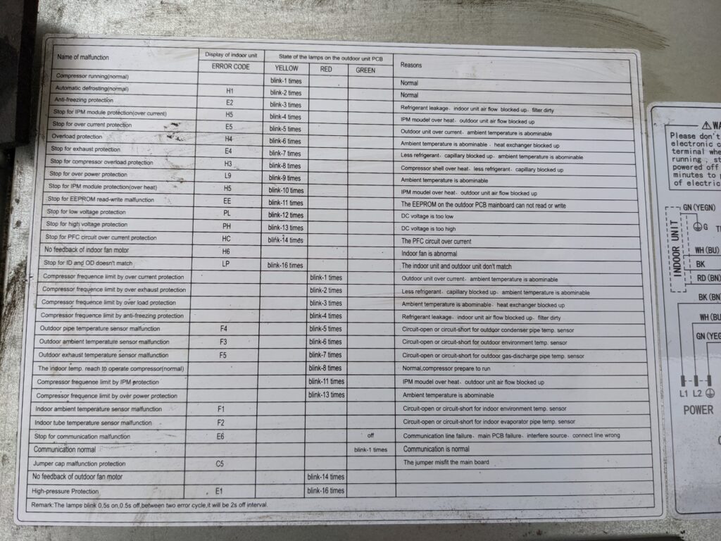
This is particularly useful, and hopefully helps others in the future as well that might be looking for codes before opening up their unit. I confirmed that the indoor unit “E1” code indeed meant that the unit thought it was in an overpressure state. Checking the wiring diagram nearby, it appears there are two pressure sensors (Normally Closed) that open when a high pressure condition occurs. Probing the two sensors on the board (OPP and OPP1) showed that there was 5V across one, and 0V across the other. OPP, plug pulled and continuity checked, was open and indicating a high pressure fault.
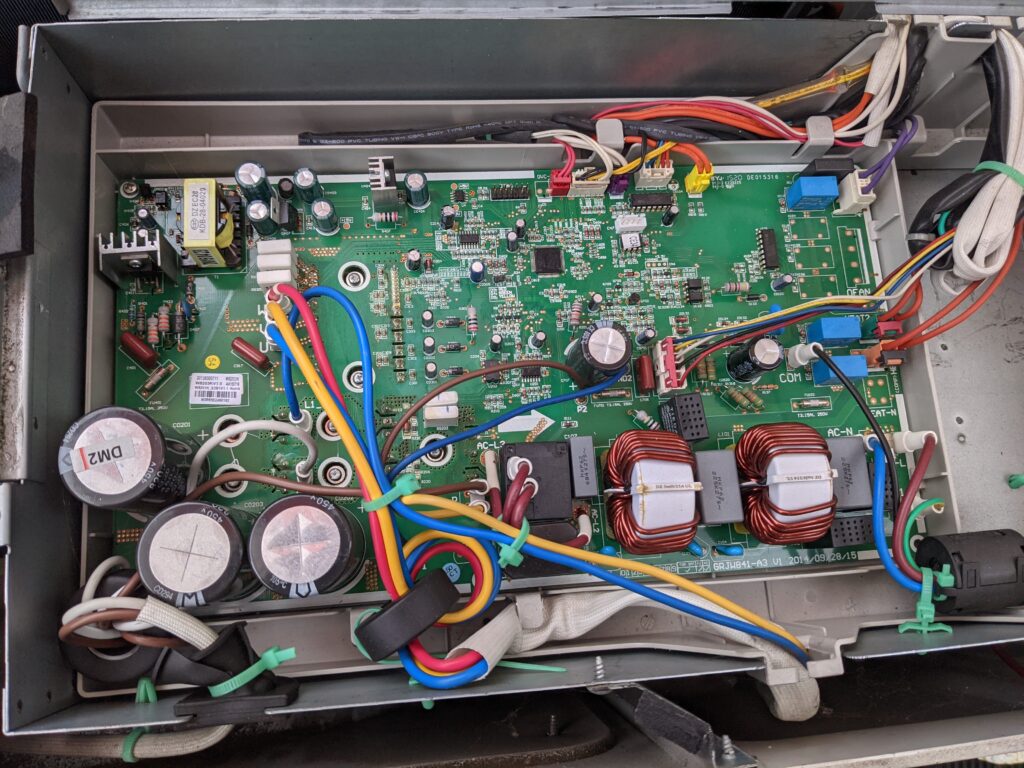
Having a closer look at the sensors, it appears that OPP has a higher pressure setpoint than OPP1. This would indicate to me that since OPP1 is not indicating an over pressure condition, OPP has an open in the wiring or the sensor is failing. To confirm this, I placed a alligator clip across the two pins on the PCB, effectively telling the board that OPP is “OK” and to start the unit. The error code cleared, the red LED started blinking 8 times (normal condition of operation), the green LED said I had communication with the indoor unit, and the compressor/fan started to run. Excellent.

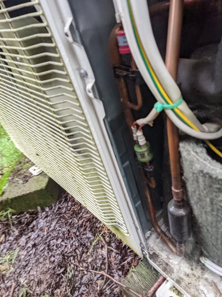
Now to move down to the sensor, I pulled the front cover off (a couple more phillips head screws) and followed the cables down to the respective sensors.
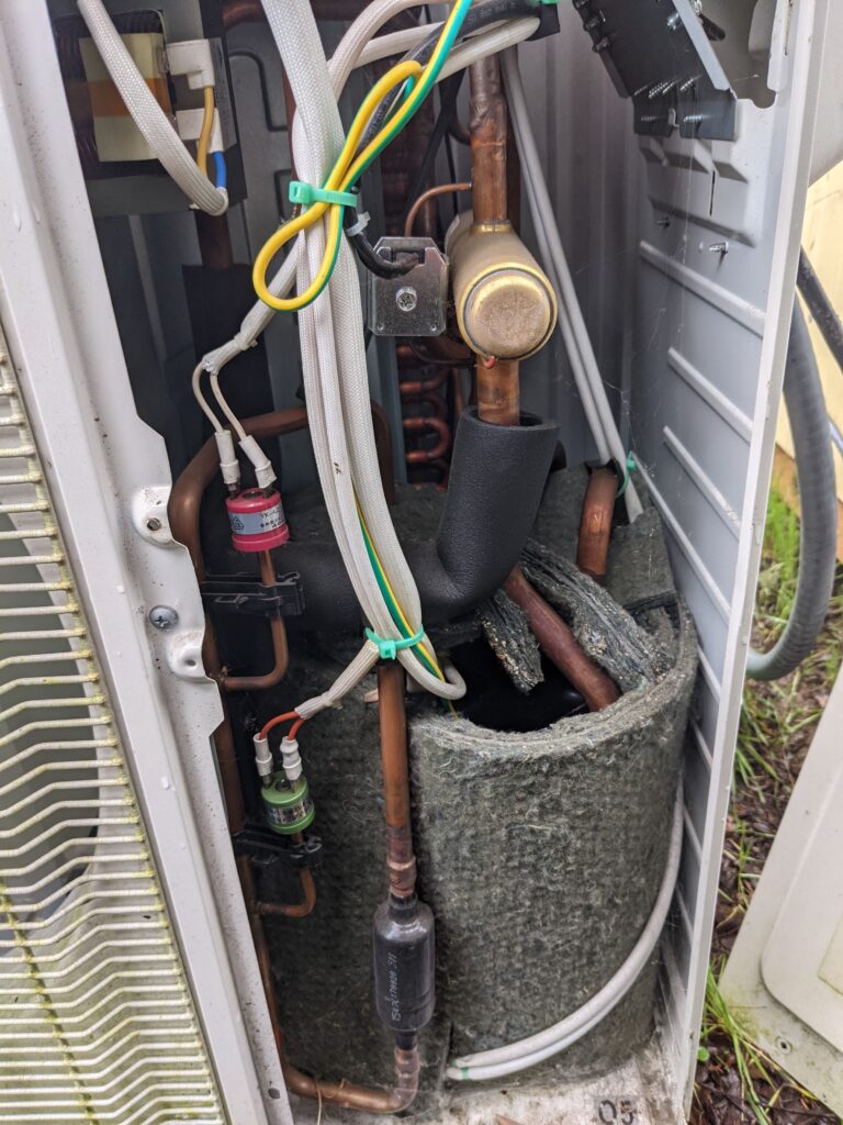
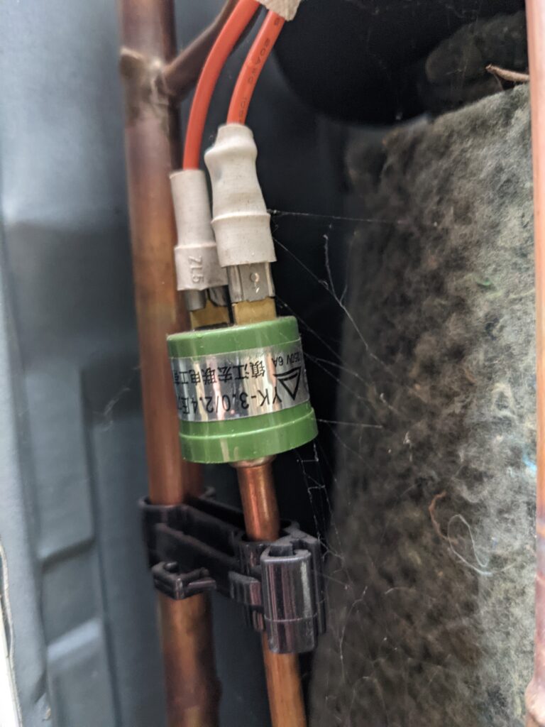
Wiggling connections, it appears there may be a loose spade terminal at OPP (red sensor) that could perhaps be causing the open condition? This line sees vibration from the fan and compressor, and was showing continuity when I checked it again after jumping the pins on the PCB. I cleaned the terminals and re-connected the sensor.
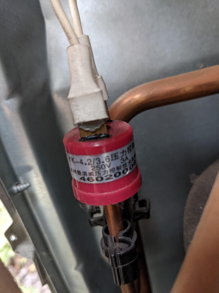
I snagged a photo of the sensor before moving forward incase I need to replace it. Unfortunately this sensor is brazed in place, so would require a full system evacuation and re-charge. This part number is a valid, and available across the web fairly cheaply (<$20)
OPP1 below tested good and appears to be working fine. No issues there so left well enough alone.
These two sensors are very easily accessed and should be not too terrible to replace if I need to do so later on. Brazing in tight quarters gets tricky so I appreciate that these aren’t buried into the enclosure, surrounded by flammable objects. I will report back later if this terminal cleaning did the fix or to expect a sensor replacement post in the near future. To keep things running (unit keeps the shop humidity controlled and above freezing) I may bypass the high pressure sensor until I can do the fix, understanding that the lower should activate first (and is unlikely to do so during the winter after 4+ years of operating normally). Thanks for following along!
I recently stumbled across and have grown interest in supporting a very interesting project inline with my interests! https://www.gofundme.com/f/powerpodspdx
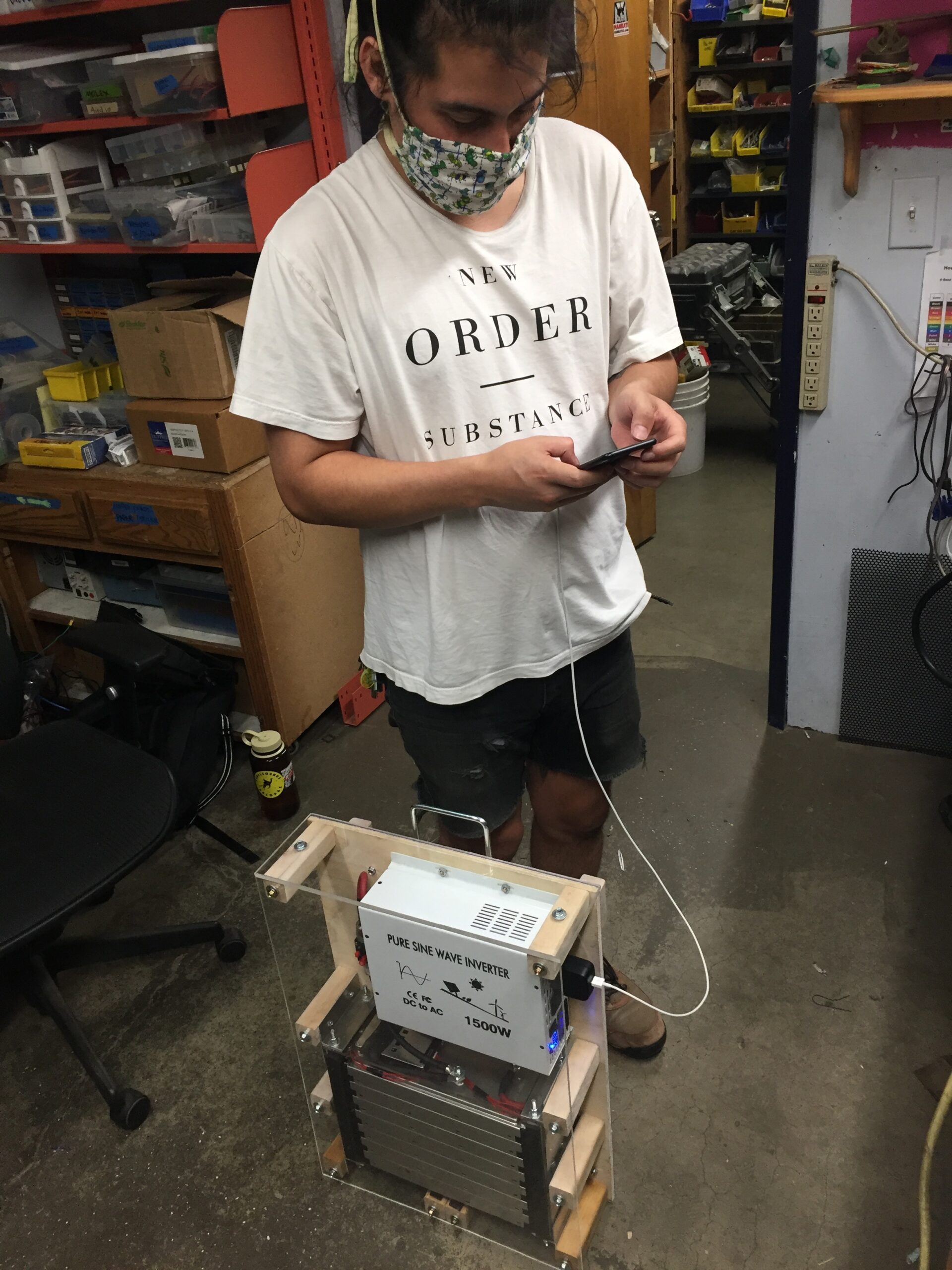
Introducing our prototype Community Power Pod, a Do-It-Yourself 1500 watt, 3000Wh portable generator utilizing secondhand battery modules from the Chevy Bolt EV. The pod is solar rechargeable and has quiet, fume-free operation, allowing it to be used almost anywhere! I’ve been helping a team of makers in Portland develop this open source community aid and disaster relief project, aimed at increasing access to this renewable technology for under served populations and those affected by natural disasters or other crises. We are working to build a fleet of these which can be deployed to support community members in need, and with the recent pandemic and wildfires that need is greater than ever. Our generator has been used for weeks now to support COVID-safe outdoor public events, fire relief efforts, and community aid projects.The power pod cost us around $600 to construct– a fraction of the price of commercial alternatives. The team hopes to build more of these ASAP, as well as share our knowledge and resources with groups in other cities so they can replicate and build upon our work elsewhere. However, at the moment we are working to find a new source for our Chevy Bolt battery modules, since the original supplier has sold out. More updates forthcoming once we can figure this out!
-CommunityPowerPods Team


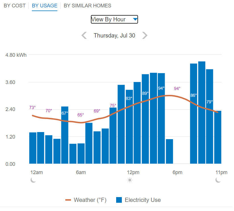
Being recently made aware of the program offered by our local utility Portland General Electric, I decided to enroll in Peak Time Rebates and try my hand at saving a few bucks on the next bill (and lightening the load on the grid during some heavy-usage times). A couple opportunities presented themselves in late July, which I partook in, however have yet to see the benefits reflected on my bill (up to $1 per kWhr saved during the event, as per the PGE website).
A day prior to the first event, I received text & email notification of an upcoming Peak Time Event scheduled for 5-8pm July 21st, 2020. I decided to see if I could move my home power usage during the event to zero without any significant fallout. With ample warning, I prepared my various systems for 3hrs+ of offline time, ensuring that battery backed devices were up to the task and that the few non-battery backed devices were moved over to independent power sources. This was fairly easy given that I’ve been creating an overabundance of energy lately but have nowhere to send it (read as – not grid tied). The only large consumers in this category were items like refrigeration, fans, etc.
5pm on the 21st rolls up and I was a little late getting home so didn’t start shedding loads until closer to 6pm. Early in the second hour of the event I had reduced my energy draw to zero, without any adverse effects. This meant shedding the AC, Heat Pump Water Heater, Spa, items like that. Refrigeration was brought onto the independent solar grid for the duration of the event. The meter stopped ‘turning’. Yay!

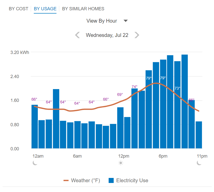
After 8pm passed, I powered back on the desired devices (AC, fans, water heater, etc) as can be seen in the graph. Temperature gain in the home was notable but not uncomfortable. My house, being built in 1915 has less than ideal forms of insulation in walls and ceiling (if any at all). Fortunately the finished basement remains it’s fairly standard 17-18C; a nice refuge if things get too warm on the main floor. I felt accomplished with the experiment and waited for news as to what my rebate savings would be (typically sent via email/text as well).
Those results never came.
For comparison, the next day (typical high-end of power load for my home and accessories).
I didn’t think much of the event until I started hearing reports that other folks were receiving their rebate information (or that they didn’t reduce enough to qualify). Another peak time event text came through, this time for the 30th of July, so I prepared once again.
This round I was able to start earlier, though still a bit behind schedule due to some visitors. Similar setup, battery backed items were easily shed and the refrigeration moved to my alternative energy source. I made a nice big dent in the power draw during the 3hour window, raising interior temperatures 3-4C but still tolerable for inhabitants. Nearly hitting the zero-power-used mark for the time period, I felt fairly accomplished.
Fast forward to 2nd week of August, and I still haven’t heard the results of my efforts. Nothing on the PGE website about my peak time events being successful (or denied)…just a blank window.

Bummer. Starting to wonder if their system ‘broke’ when it saw the zero and/or too-near-zero values that it flagged it requiring review before applying rebate. Given that the average layperson isn’t familiar with the small loads associated with wall-wart style power packs or smart device draw even when off, I guess I could understand. So I called PGE up.
The associated I talked to (Robert) was understanding and although a bit confused himself, had access to internal FAQ materials that advised him to let me know that zero usage during a time period makes the program assume there was a outage (or something of that sort?) that would render the data ineligible for the PGE Peak Time Rebates program. He kept asking “did you turn off the breaker?” Having not found anything indicating that zero usage would invalidate the rebate option, I was (and continue to be) confused but realize that this person likely won’t have the solution I’m looking for. I asked that if were able to flag my account for review AND also please present more accurate terms and conditions for the program on the website, it would be appreciated. Frustrated, but not going to take it out on a support person, I completed the call and pondered my next move.
Twitter?
I logged into my old Twitter account and searched for Portland General Electric, ready to shine some public light on my experience and see what comes of the effort. With little to loose other than them possibly deciding they don’t want to provide me energy anymore, I figured it was worth a shot.

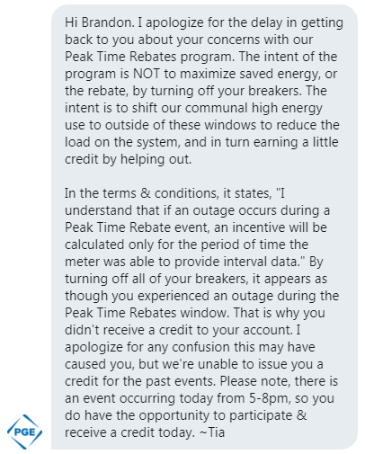
I was contacted publicly by a representative (Sonja) who explained eloquently:

A bit of back and forth ensued, and the end result was that I was forwarded to Elaine, who was putting my situation in front of an Advisor and they would be contacting me soon. Fingers crossed for some resolution? I’ll update as I find out more.
Update:
Pinged them again on Twitter and got a reply later that day:
Even though my meter was indicating data (in some cases zero, some – reduced usage) apparently PGE will flag the period as an ‘outage’ if there is zero kWhr used during any of those hour blocks. This decision is in reply to disclosing that my ‘essential’ home loads were powered alternatively and anything battery backed was effectively ‘shifting’ the draw outside the window, charging batteries after and precisely meeting the goal the outlined for the program.
The summary? If you’re going to save energy, make sure you don’t save too much.
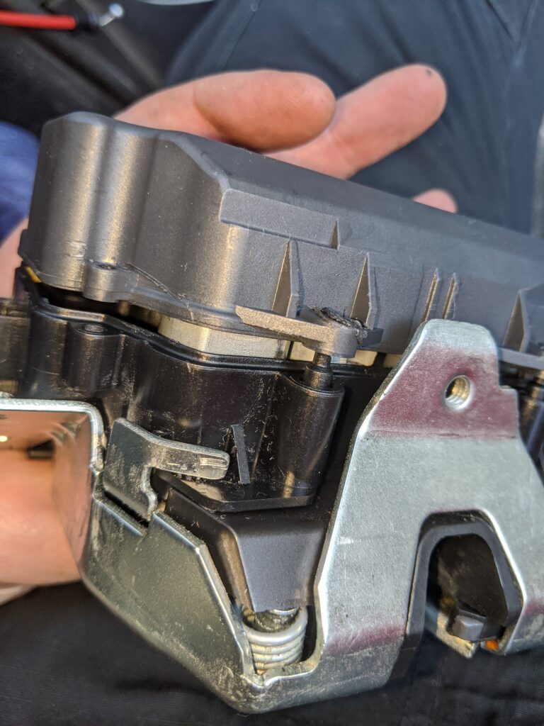
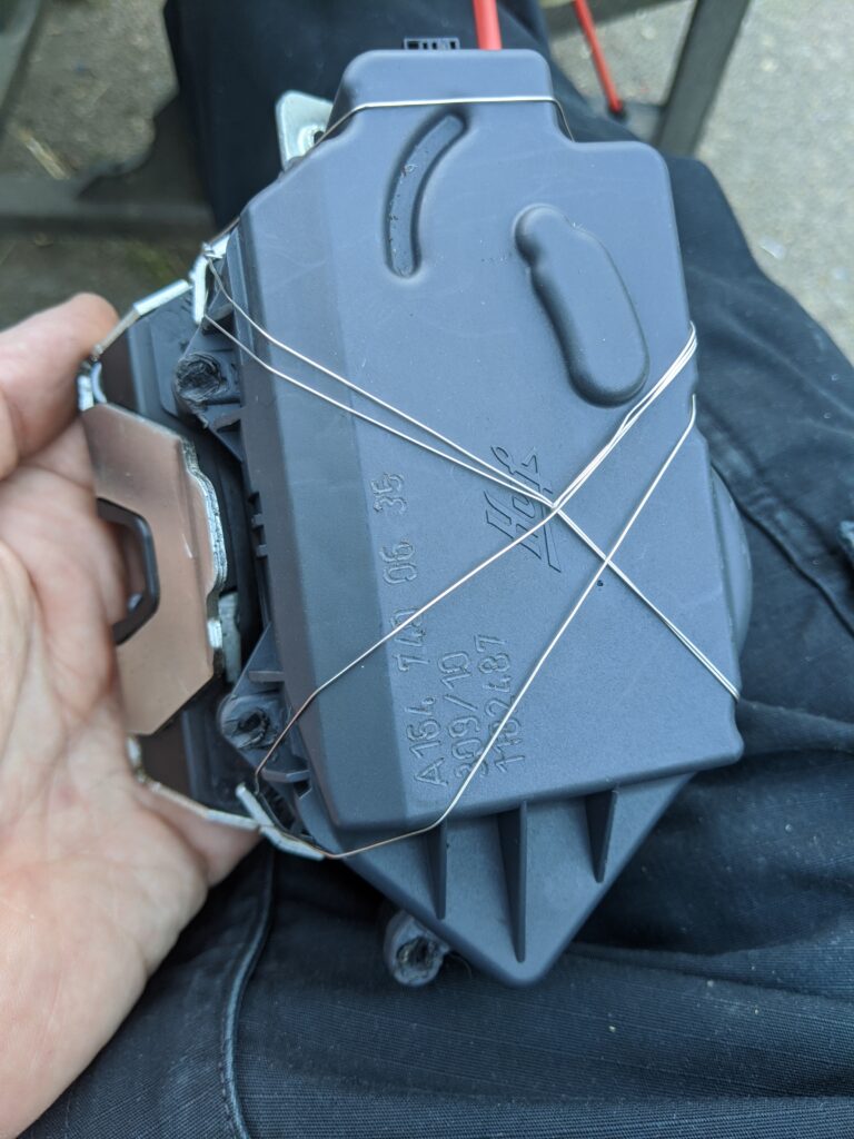
A common problem with the w164 chassis is the auto-pull-in electric rear hatch latch. These are known to fail, especially if the user operates the door without using the open/close assist hydraulic system (button/remote versus lowering by hand). The end result is a rear door latch that won’t open, close, or latch properly resulting in error messages and an unsafe condition. These little latches are very spendy and have gone through a few revisions. Not being one to give up easily and buy new parts, I wanted to see if I could have a go at fixing mine. The issue as I saw it first appear was that the door wouldn’t ‘pull in’ and fully latch. No amount of forcing would close/latch the door either so this was a safety issue worth fixing immediately.
I tore the rear panel off the rear hatch door, removed the three Torx screws, the emergency exit latch cable, disconnected the latch mechanism and pulled it out. What I found is below…a device that you must destruct to open and is not able to be re-assembled without additional ‘stuff’.
I started by cracking open the upper ‘plastic’ case by removing the tops off the plastic welds. A myriad of parts were inside, hopefully able to be replaced properly without issue when I’m done. The bigger issue was removing the middle body from the lower unit, as there is a flag arm/cam that engages with the metal bits of the latch and this has to be indexed ~200 degrees around to pass through an ‘assembly slot’. They clearly made this device to only go together, not come apart. Some tinkering with a few probes and flashlight I was able to rotate the mechanism and fully disassemble.
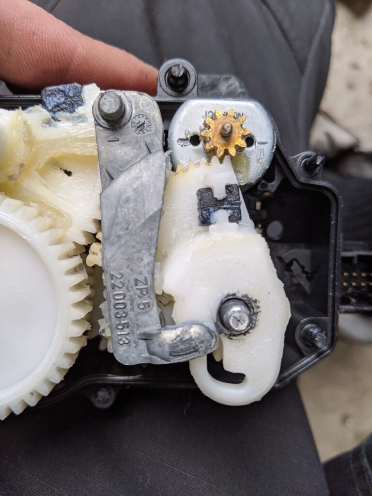
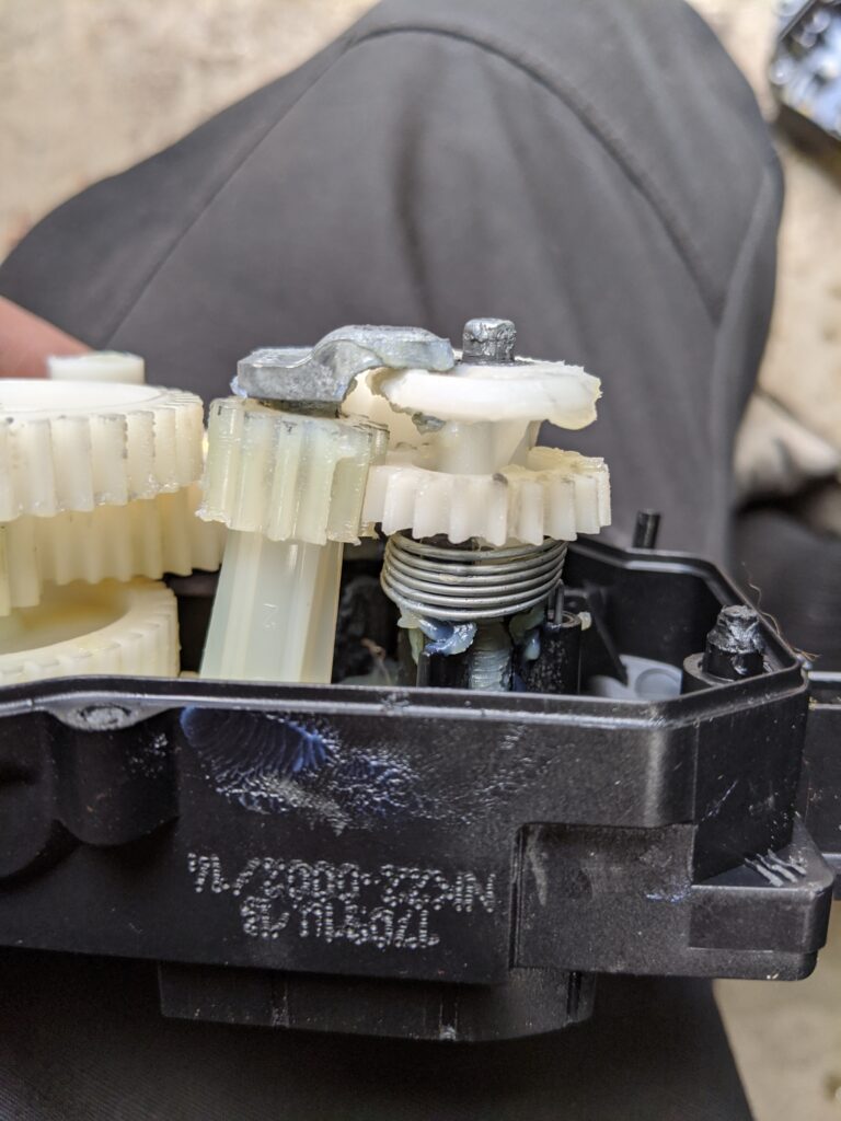

Lots of grease, complex components, but fairly well built. I started to poke around and found the issue fairly quickly, I had two pieces where there should have been one. I unstacked the gear train, spacers, etc and set them aside on a clean surface and extracted the closing mechanism shaft.
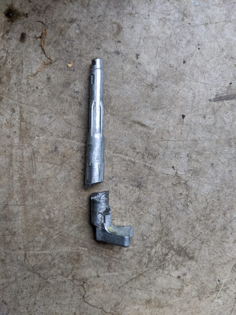
This item had a pretty ugly shear failure right where the shaft leaves the housing (and associated bearing support). That is a difficult fix as ‘gluing’ this joint would just result in an immediate failure. I’m going to need to add some strength, or build an entire new shaft out of something else. I opened to try the former.

I chucked the two pieces up in the mill and started removing metal. I also drilled the center of the shafts to fit a piece of drill rod for reinforcement purposes when it came time to assembly. This shaft needed to resist some pretty knarly torsional loads so I drilled deep.
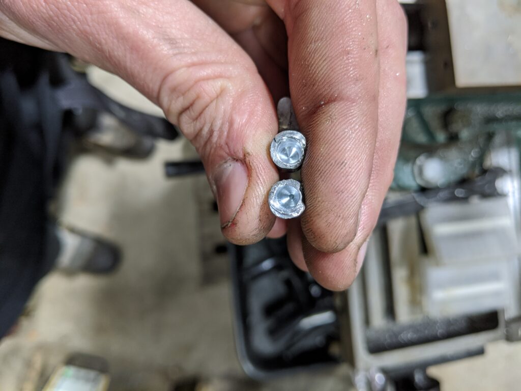
Tossed in the drill rod, did a dry test fit, and things are looking pretty good. Getting the bores perfect drilled/aligned was a challenge HOWEVER the gear that resides on the bottom (cam) side of the shaft has nothing specific about what it indexes with. The result was rotating the two halves before assembly to achieve the best co-axial configuration, making sure the two halves don’t push too far apart due to the un-clean shear.
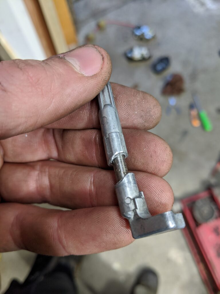
Now it’s time for the JB Weld. I mixed up a small batch of the Quick Set after visiting my friend in the middle of the night, me unable to find my stash of two-part epoxies. Little bit of helping hands later and confirming the coaxial rotations, I assembled and confirmed length against ‘expected’ length gathered from pre-milling measurements.

Once the shaft had some time to set up, I re-assembled the whole stack and indexed things back in their proper locations. The largest remaining hurdle was figuring out how to re-secure the upper housing plastic button welds that were now gone. I tried melting things but ultimately the solution was a bit less elegant.
The latch has been performing well for a number of weeks now, hopefully continuing to do so for quite some time. I have my eyes out for another broken latch assembly to repair and have at the ready if the need presents itself. While the construction of the latch is fairly decent, the serviceability is far below my expected standard for Mercedes hardware, though this is a Huf brand mechanism (the supplier for Mercedes latches/locks/keys).
Thanks for reading along!
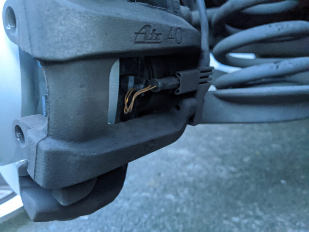
After many weeks of “Brake Pads” warning on my city driver, it was time to install the new rear brake components I’ve been sitting on. On the docket were two new rear rotors, rear brake pads, and wear sensor.
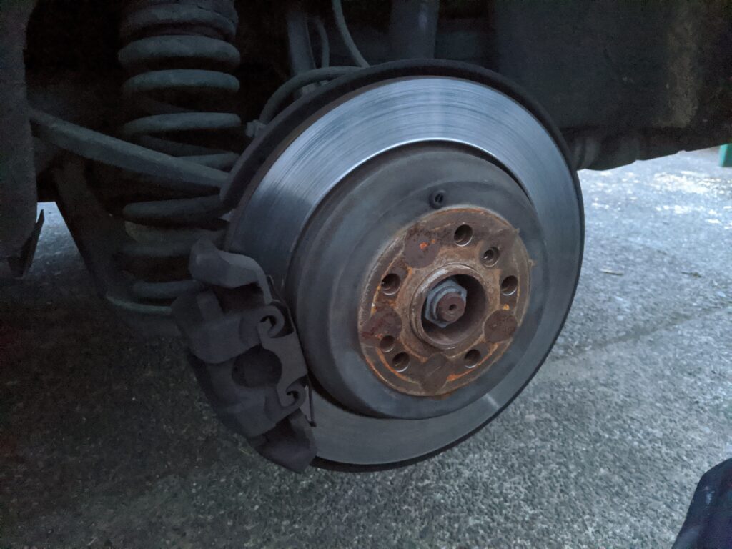
After removing the caliper, safely hanging not by the hose, pulling the pads, and removing the rotor retaining bolt, I pulled the rotor out and off the car. I compressed the caliper piston back in to allow for installation of the newer-thicker pads.
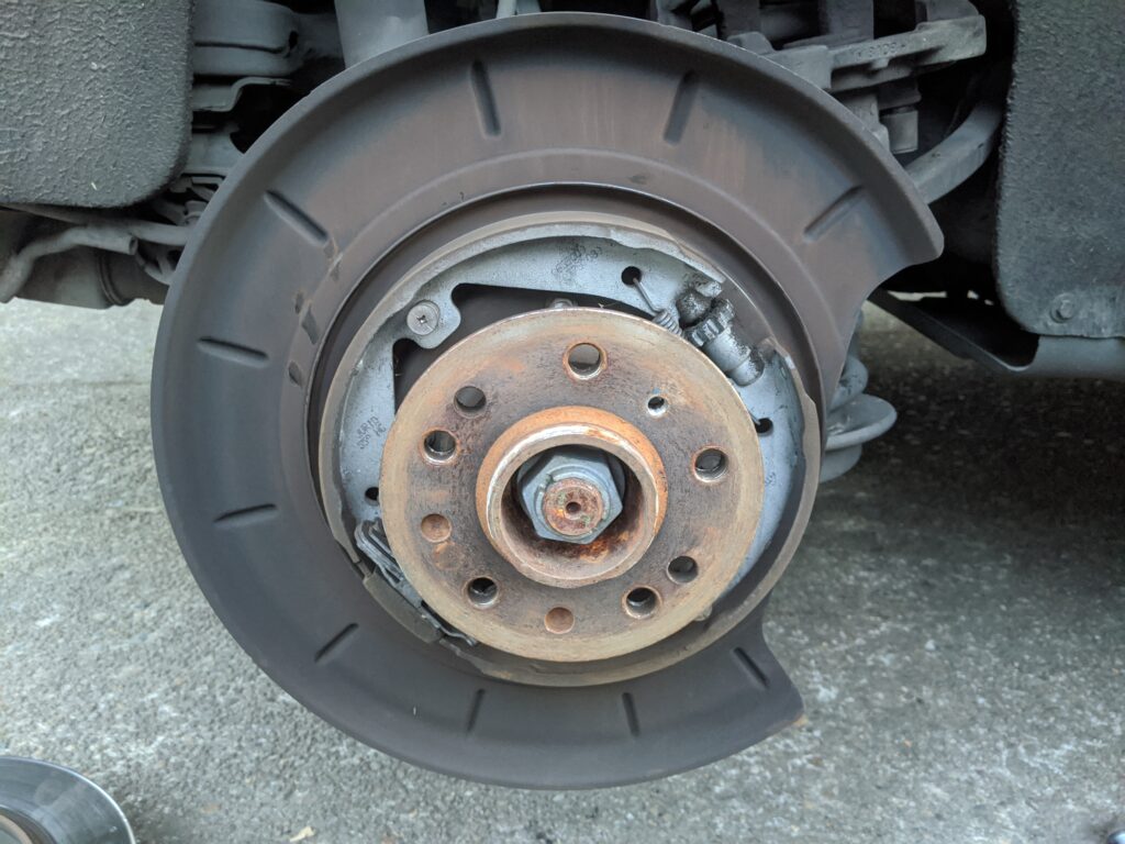
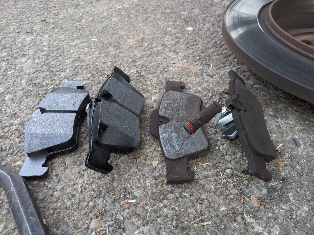
I confirmed free movement of the emergency brake adjuster and blew all the loose dust/etc. out. This will enable me adjusting the emergency brake ones the new rotors are on. Inspected the old pads and wear sensor, definitely touching down. This wear sensor busted as I was trying to pull it before photoing.
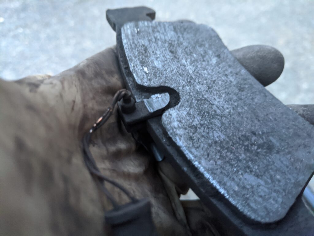
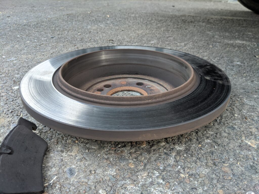
Comparison of the old pads and new, quite a difference. Note that the wear sensor isn’t installed yet in the new pads.
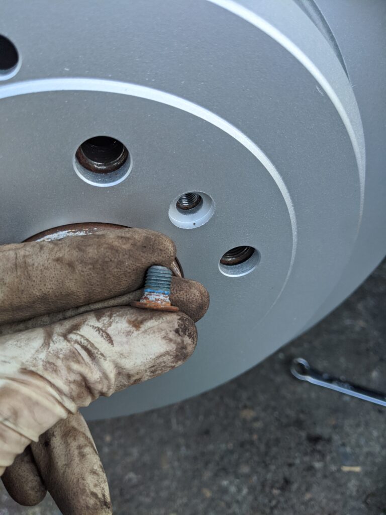
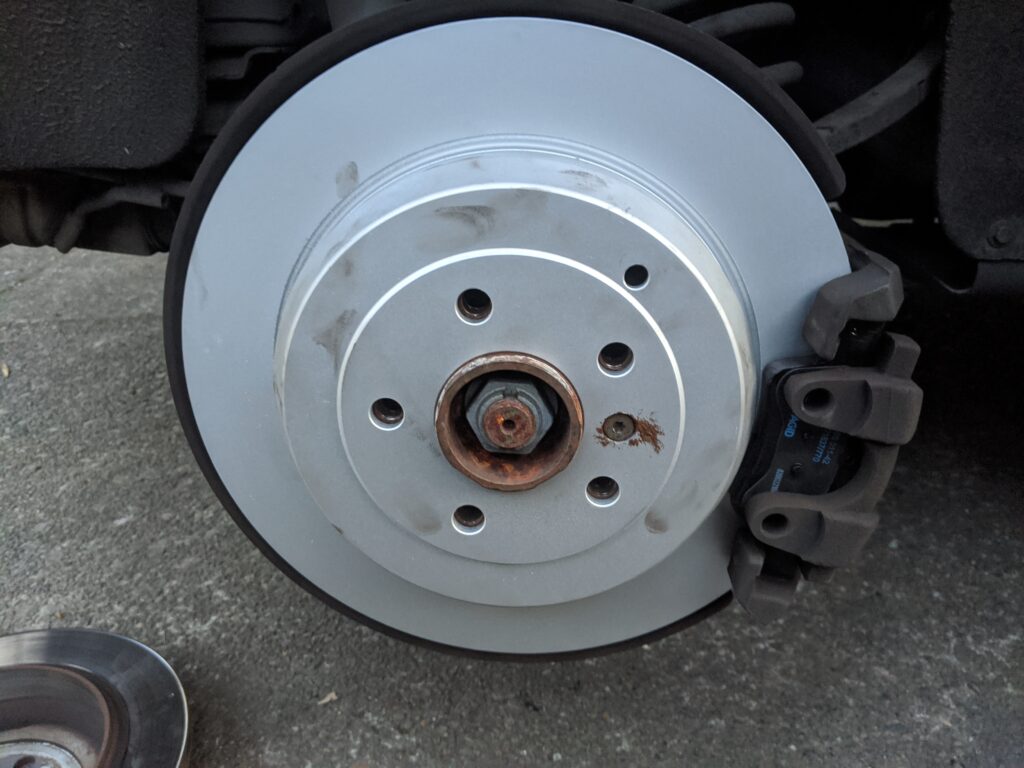
Reassemble the brake system, rotor first and install the small bolt. I tend to put a small amount of anti-seize on the touchdown points on these because the wheel retains them and they’re only there to hold things in place and indexed while the wheel is off/loose. Additionally they tend to be VERY hard to remove. A little blue locktite works too.
Caliper back on next, compressing the piston to allow for the new pads is important. Push slowly, and sometimes fluid may need to be bled while doing this to prevent issues with up-stream ABS components. Checking out the caliper slides while here is not a bad idea either. These single piston calipers need to ‘float’ on the rotor to work properly. Here in the PNW our cars don’t get heavily salted so most of these components are good for the life of the vehicle if driven and maintained regularly. Check condition of hoses as well while here. Adjust the e-brake through a lug-bolt hole…tighten until rotor won’t turn then back off until just barely dragging. Confirm after doing both sides that the e-brake pedal engages near the top half.
Remembering to install and re-connect the wear sensor is important. Routing the wires where they will not get cut up or damaged by the spinning rotor is also important. Don’t forget the anti-rattle clip on the caliper when you’re done!
Thanks for joining in for what was a pretty straight-forward repair, documented for your pleasure.
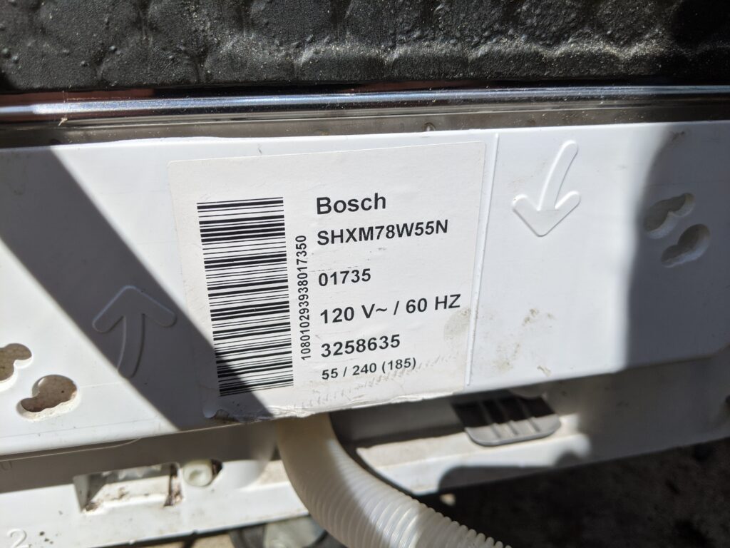
On the block today is a Bosch SHXM78W55N Dishwasher I picked up used for $40, claiming that it ‘leaked’ and ‘they were done messing with it’. A quick internet search showed this to be a fairly new model, still available, at painful $900 new locally. For me, this was worth a gamble, especially considering my existing LG Dishwasher that came with the house was worn out, needing parts and a pump rebuild to the tune of over $200+ and it still being a lower end/older unit.
I went and picked it up, brought it home, and plugged it in.
After plugging things in, the front panel wouldn’t turn on and it appears there might be more than an issue with ‘leaking’. The bottom pan was definitely wet and I noticed a Styrofoam float sensor among a bunch of dust/goop collected in the bottom.

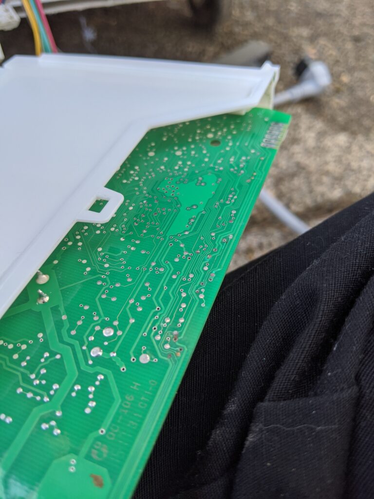
I popped the covers off the control PCB and started looking for issues. Immediately I found something concerning….but expected.

Looks like the PCB took a bit of a swim in some moisture while power was applied. Some quick pokes with the DMM revealed that most of the discolored top-to-bottom vias were no-connects. This is very commonly found in non-coated boards that have gotten wet, the water loves to wick in these holes and corrode away at the copper.
And as a reminder, don’t forget to take pictures of how those cables are attached…sometimes the manufacture service manuals aren’t good about helping you find the homes after things are ready to reassemble.

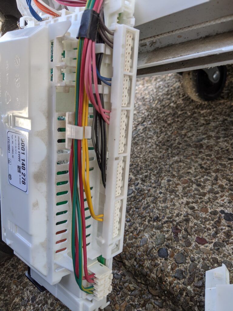
I pulled the board into the lab and started doing continuity tests, finding a handful of broken traces/vias that needed re-built with stranded wire. Generally speaking a via can be replaced with a fine strand of wire through the board and soldered on the top/bottom after removing some of the solder mask of the annular ring. If these are dissolved/gone, the strand can be taken upstream to find good clean copper under the solder mask. The issues seemed contained to this bottom edge of the board, interestingly enough probably held there by the boards water protection housing!

I cleaned up these housings once done repairing the board and started re-assembly. Before stuffing the control board back in, I cleaned the pan and looked for the source of the original problem…remember the leak?

Following the little stream marks across the pan, it appears that the source of the leak was the input connector, likely never tightened properly or overly stressed by a poor install. A small catch trough under this connection point collects any water and brings it to the center of the pan so that the ‘leak detector’ float can eventually be lifted and alert the user before their floor gets wet. Improper installation likely caused this units failure and consequently to my doorstep for repair and eventual use; even if requiring a little attention first.

Thanks for following along for another repair!
At the time of writing this, I’ve had two Pixel 3XL and three Pixel 3 come across my desk, with a poor batting average for reliability. Failing front cameras, USB-C port issues, and now compromised IP68 rating resulting in a device failure. I enjoy the use of this product, however my confidence in reliability and build quality is wavering.
The adventures of my current Pixel 3XL (a warranty replacement from my prior due to a USB-C issue) start with an accidental introduction to what should have been a tolerable amount of water (<1m, <1min). It appears upon further investigation that the ‘Refurbished’ units delved out by Google and [in my case] Verizon have likely been opened up from factory, and as such no longer meet their claimed IP68 rating. The entire rear glass (the point of access) is glued in place with a complex perimeter of elastomeric black tape goo that I wouldn’t expect to seal right unless new on the factory floor. While achieving access to the internals wasn’t too bad, I suspect my experience was unique with this unit being ‘refurbished’.
Post moisture exposure, realizing what had happened and that the phone WAS in fact upset and water had reached the internals, I immediately powered it down and started shaking water out of the handset. Removing the SIM card tray helped significantly with this process as it has a gasket on the outside edge of the tray, meaning the SIM card lives inside the protected environment. A remarkable amount of water came out of the phone (bad enough that when shaking could hear it sloshing around). No water was visible at the screen level however all cameras, flash, and other sensors were clearly wet.
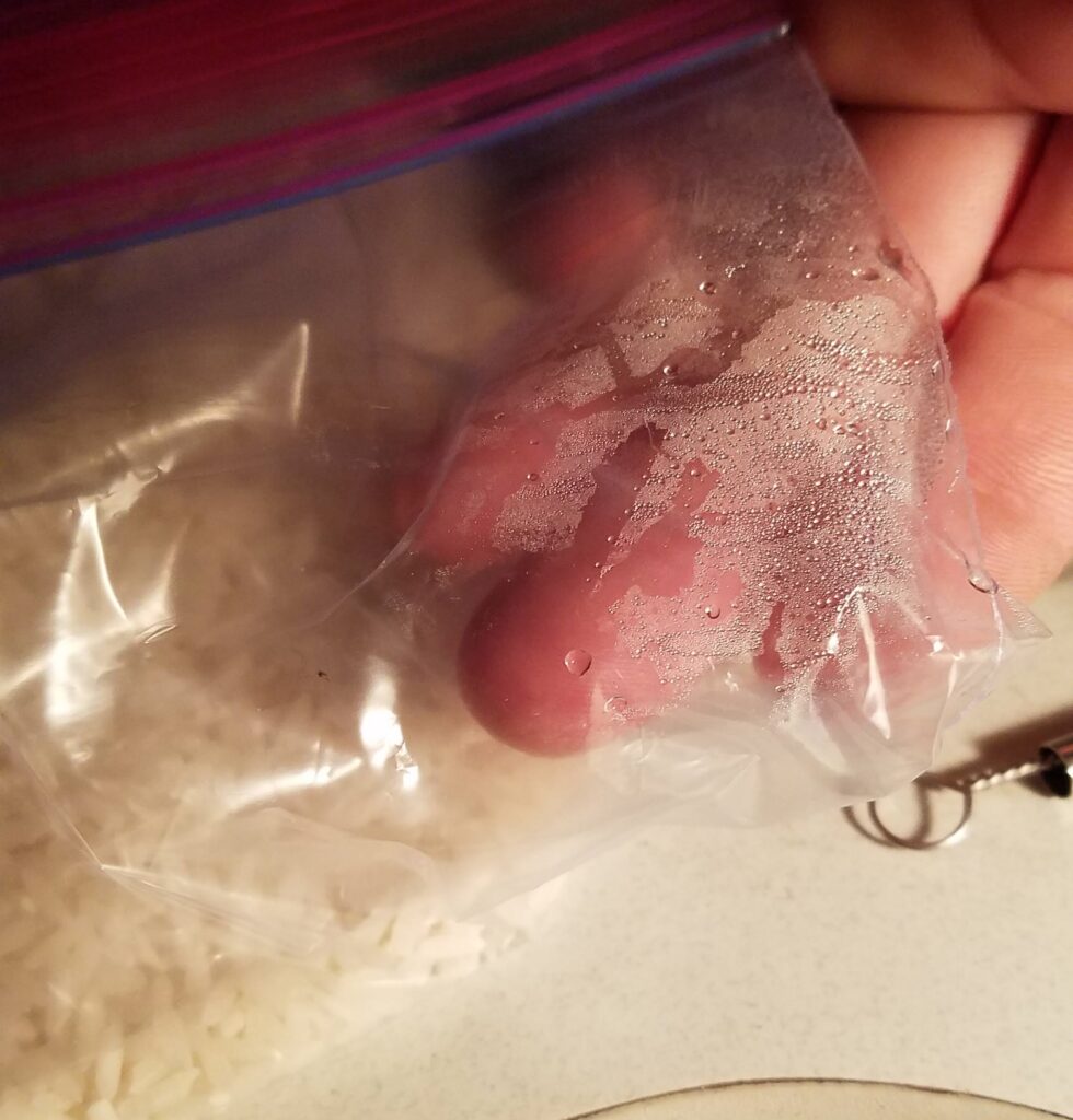
I placed the handset in the usual bag of rice, not realizing that said rice was apparently already exposed to moisture. Adding a 25W incandescent desk lamp above the rice+handset bag to help with the process showed me just how damp the rice already was.
Giving up on the rice, and realizing that the moisture was just moving around inside the handset, I decided to remove the back glass and see if I could help the process along. A little poking online informed me that a good heat gun and some gentle prying around the perimeter opposite the buttons will allow the back to come free and hinge on the opposing side (where the cable for the fingerprint sensor moves up). Some improper tool usage and a hot handset later, it came free. Lifting a small piece of Kapton tape and a FFC connector toggle allowed me to unplug the fingerprint sensor and remove the back completely.
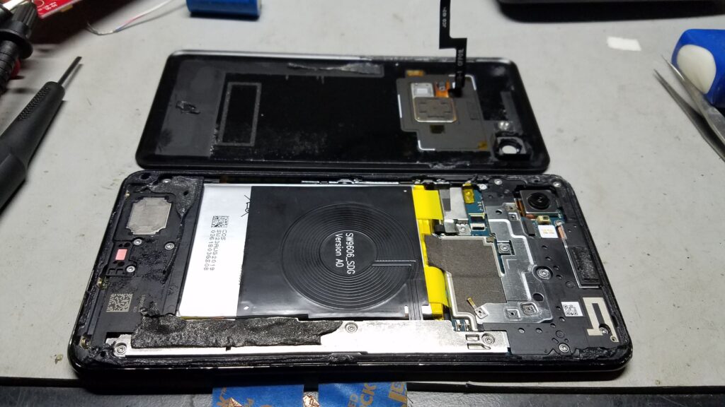
Can see to the left of the photo above that the moisture indicator has gone pink, in-case there was any question about water ingress. A little poking around online at some tear-down photos helped me locate the OLED connector location (under this strip of silver metal in the photo above). With a screen gone green, I figured something at the drive end was upset and should start there. A screw is hidden under the black adhesive, go digging.

Initial inspection looked grim. The PCB showed signs of power-on corrosion around the higher-voltage signals for the OLED screen and at the battery connector. Electrolysis is not out friend, the metal will disappear in short time given average water/moisture and enough voltage. I disconnected the battery connector and then the display (large rectangular connector center of image above). Utility knife blade for scale.
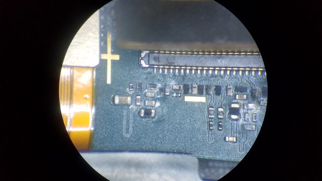
As visible above, things got unhappy here. Some poking around with my finest needle tip Pamona probes and a Fluke 87V told me everything I needed to know, the microscopic resistor centered in the photo above was still a resistor, coated in carbon and the remnants of it’s solder, no longer connected on the bottom lead. My experience in the past has been very poor getting SMT components that have undergone such corrosion to fully re-solder (usually ending with the ends/terminations ripping off), but I tried anyway. The finest Metcal probe and UltraFine tweezers were still gargantuan under my 10X WF Bausch & Lomb StereoZoom at full magnification. If you don’t own a high end iron with ultra-fine tips, don’t bother getting it anywhere near a modern cell phone PCB unless you’re expecting to toss it in the bin when you’re done.
After spending a good amount of time attempting to bring the resistor back home, even cleaning the landing pads and moving to leaded solder, it wasn’t going to happen. The resistance measured somewhere around 2-3ohms so I decided to see if a direct short of wire would do the trick. I picked a single strand out of some wire, tinned it, and stuck it down to what was left of the mangled pads. Even with the Metcal doing it’s best, the PCB’s don’t take kindly to anything but the soft caress of a pick-and-place/reflow-oven touching them. It is VERY easy to destroy traces, lift pads, break vias, and otherwise back yourself down a path of no repair.
Shorting wire placed, corrosion otherwise gently brushed of the board and potential shorts cleared, I reconnected the battery (and USB-C charger at this point) to see if it would come alive, sans green tint.
IT WORKED.
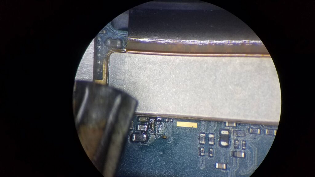
Barely visible in the mess of flux is the thin strand of wire bridging the pads. Just to the right and below the other components nearby is the removed [charred] resistor waiting to fall off the board into my carpet when I picked up the phone.
Overall the remainder of the phone internally fared alright, paying specific attention to clearing corrosion around any connectors, higher voltage areas, or burned spots. Under the battery flex-to-board connector was particularly unpleasant, and might explain why it drained so fast after getting moist.
A particular challenge was clearing water from in front of the front facing cameras. The ‘left’ camera (opposite the buttons) was very fogged regardless of heat and air application, returning after things cooled down. Before buttoning the phone back up, I removed one of the hold down screws, loosened the other, and gently lifted the offending camera far enough off the front glass to let the moisture slowly dissipate. Some heat, dry air, and waiting later, I put it back in place and secured it, confirming things were dry and clean. The rear camera fit nicely back into it’s void and appeared to not get any contamination on the lens.
I re-secured the cover after powering off the handset, connecting the finger-print reader, powering up, and confirming it still worked. I know there’s no chance I’m going to get close to IP68 with how the handset was already compromised due to being a ‘refreshed’ unit [likely a early unit that needed it’s rear camera replaced] so I used what glue was still usable, applied heat, and pressed everything back into place. Of particular note, I specifically attempted to avoid heating the battery as much as possible, knowing that these do not appreciate any extremes.
Upon further research, it appears that for a good number of modules within the device, replacement/service requires ‘splitting’ of a glued together speaker cavity, the reassembly thereof prone to create another major place for water to enter the handset if not done carefully. It appears that it is best to not rely upon the waterproofing, especially if you suspect the handset has ever been opened or any of the myriad of seals compromised. Water proof case might be the better option if rolling those dice.
Handset seems fully functional days later, save for a few new little scratches around the bezel on the back side (easily hidden by my Spigen case). The likelihood of water wicking into the back cover area is now greatly increased with my re-use of the old segregated glue so I’ll be on the extra careful road when it comes to placing the phone anywhere it might get more than sprinkled on. There seems to be no adverse effects associated with the resistor removal and replacement with a shorting wire. Time shall tell.
Thanks for reading!
These were harvested from various sources that no longer allow them. Cudos to the rightful owners…may your legacy live on!
Hosted on google-drive.
dickbutt.zip has all the .stl files I have within. Chess Set pieces and a dickbutt 2D -> 3D conversion.
Cheers!
https://drive.google.com/file/d/0Bx_qKzyNetMDRi1lSUNnXzh1RGc/view?usp=sharing
Some very basic (but very useful) notes regarding RFID products on Chinese ebay auctions for RFID readers. This includes wiegand receivers. This is mainly for the cheap RFID readers/cards/etc. found on e-bay.
The standards listed (14443A, M1Card, etc.) are used randomly even though the devices may not be compatible. It appears the fall-back is the ID/IC standard for whether your card is LF or HF. The likelihood of a dual-band reader existing on ebay is VERY VERY slim.