Decoding Chinese RFID Ebay Auctions

Some very basic (but very useful) notes regarding RFID products on Chinese ebay auctions for RFID readers. This includes wiegand receivers. This is mainly for the cheap RFID readers/cards/etc. found on e-bay.

  • If it says “ID” anywhere in the ad, 125Khz
  • If it says “IC” anywhere in the ad, 13.56Mhz.

The standards listed (14443A, M1Card, etc.) are used randomly even though the devices may not be compatible. It appears the fall-back is the ID/IC standard for whether your card is LF or HF. The likelihood of a dual-band reader existing on ebay is VERY VERY slim.


Droid 4: 4 Gold Pins Under Rear Cover – Successful 5V Charging at 1.5A

Hey all,

Connected a current limited power supply to Gnd and Vin on the back of my Droid 4 (pin lower right = gnd, pin lower left = Vin) at 5.0V and I had literal fast charging occurring. Screen showed charging, amperage was around 1500mA to start scaling down to 1300mA-1100mA as it reached full charge. It seems to pass through the Lithium Ion battery charging circuity so appears to be a safe way to dump in lots of power. Obviously these pins are designed to pick up power from the rear inductive charging cover that Motorola produced, but I wanted to try just pure 5.0V power.

I’m thinking of grabbing some extra rear covers and making up some drop-in charging stations or alternative inputs (like solar/etc.)

Nice to get away from having to charge on the USB Micro connector.

This seems like a VERY good thing if someone was building an external battery pack that fit onto the phone (like the one for the iPhone)…you could power it on, charge via this connector, and shut it down whenever you liked. The power draw on the phone drops off massively once it is charged so if you started with a full charge, it could float the battery all the way to empty.

Time to experiment 🙂

Again, for reference:

Bottom right (when viewing back, camera at the top):
Gnd is Lower Right – Nearest the microUSB connector
Vin is Lower Left – Opposite side from Gnd on the bottom row

Don’t hit it with too much voltage! I limited myself to about 4.8V and 1700mA max. 🙂

Cheers,
MIRT

10 3.__ EMERGENCY VEHICLE DETECTOR SYSTEM
Each traffic signal shall have an emergency vehicle detector system which shall conform to the details shown on the plans and these special provisions.

GENERAL
Each emergency vehicle detector system shall consist of an optical emitter assembly or assemblies located on the appropriate vehicle and an optical detector/discriminator assembly or assemblies located at the traffic signal.
Emitter assemblies are not required for this project except units for testing purposes to demonstrate that the systems perform as specified. Tests shall be conducted in the presence of the Engineer as described below under “System Operation” during the signal test period. The Engineer shall be given a minimum of 2 working days notice prior to performing the tests.
Each system shall permit detection of 2 classes of authorized vehicles. Class I (mass transit) vehicles shall be detected at ranges of up to 300 m from the optical detector. Class II (emergency) vehicles shall be detected at ranges up to 550 m from the optical detector.
Class I signals (those emitted by Class I vehicles) shall be distinguished from Class II signals (those emitted by Class II vehicles) on the basis of the modulation frequency of the light from the respective emitter. The modulation frequency for Class I signal emitters shall be 9.639 Hz ± 0.110 Hz. The modulation frequency for Class II signal emitters shall be 14.035 Hz ± 0.250 Hz.
A system shall establish a priority of Class II vehicle signals over Class I vehicle signals and shall conform to the requirements in Section 25352 of the California Vehicle Code.

Webasto AT2000ST Service Manual

Webasto AT200ST Service Manual (LIT9010439B)


Interesting note on this heater:

Recently ran some bad fuel through mine and unfortunately found out that the fuel metering pump does NOT like ‘thick’ fuel or algae running through it. These are often heater-specific fuel metering pumps and sealed units.  Acquired a replacement on e-bay and upon installing it found that the heater was throwing a glow pin fault code. Ran the diagnostics to find that the glow pin resistance was appearing ‘too low’ to the heater (even though it still turned glowing hot) so it would shut down.


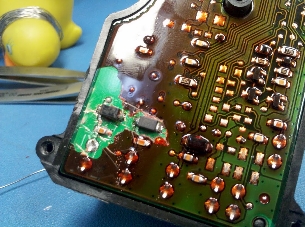
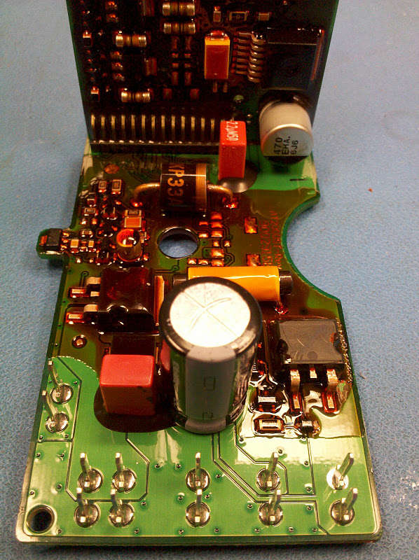
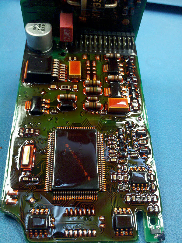
I first found that there was a direct short showing between ground and the glow-pin source (through a FET to +12v). After analyzing the control module, I found a reverse protection diode had failed to short (probably the product of me trying to investigate the glow-pin operation and shorted/powered something). I replaced this with the reverse protection diode for the fuel metering pump and used a misc. SMD diode that I had on-hand to replace the failed one for the metering pump (a much less sensitively measured device). Now that the controller wasn’t seeing a short, I merely had to be concerned with the high (.6-.9ohm) resistance of the glow pin upsetting the controller. Book specifies somewhere around .4ohm.

I added two 21W light bulbs (an increased 2.4A load @ 12V…about 29W) and found that it didn’t complain about the resistance. I figure this fix will only last so long as the glow pin apparently is showing sings of giving up the ghost. Not very impressive for a heater that has less than 100hrs on it. The proper ‘fix’ if the glow pin is actually good (fault with the heater’s measurement circuit) would be to install a couple 15-20W 20ohm resistors in parallel to shed the load in a non-illuminating way.


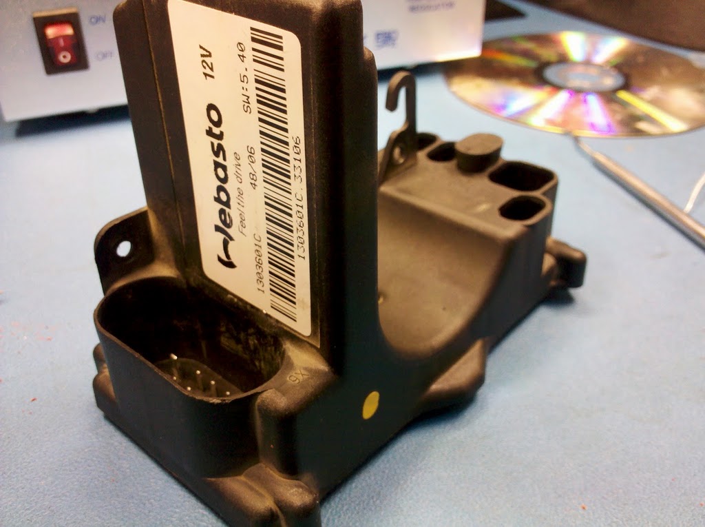
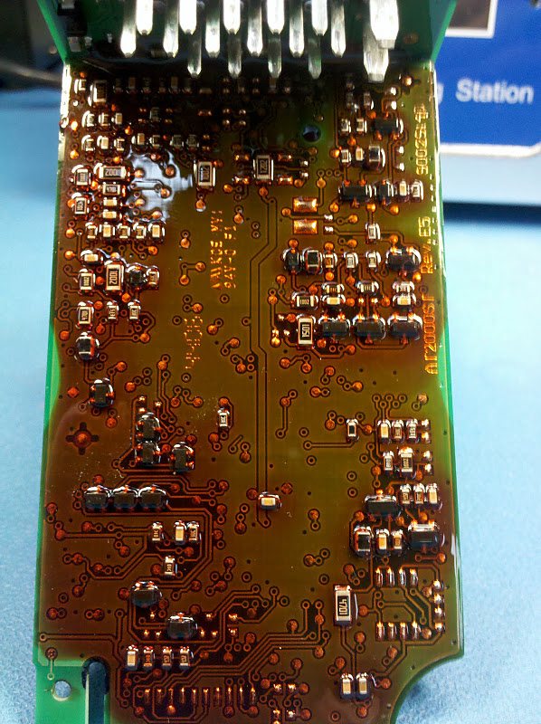
Photos of the Webasto AT2000ST Control Module

MEP-006A Exciter Diodes

Here are the two diodes I selected to replace the failed ones in my MEP-006A Military 60kW generator.

http://www.mouser.com/Search/ProductDetail.aspx?R=1N1190Avirtualkey66430000virtualkey905-1N1190A

http://www.mouser.com/Search/ProductDetail.aspx?R=1N1190ARvirtualkey66430000virtualkey905-1N1190AR


You would need x3 of each and I recommend getting a spare if you aren’t familiar with proper torque and are prone to breaking studs off components. One is a reverse connection of the other (designed 1NxxxxR)


Specifications:

1N1190 / 1N1190R Data Sheets


Three of one type are on one side of the aluminium rectifier mount, and the other three are on the other side. Make sure you use plenty of thermal conduction grease when making the connection.