Mirage Magnum Inverter 18 Repair – E1 Error

In my home shop I have installed a new-to-me-but-used Magnum 18 mini-split so that I can have heat and AC while working. I picked up this unit very cheaply, having been uninstalled from what I assume was a grow operation. While it required some deep cleaning, the unit was otherwise spotless and for the price, a steal. Getting a new lineset connected up, charging, and testing is a story for another time, however I have recently had some issues with it that I wanted to document.

Occasionally, especially during winter, I would start getting E1 codes when asking the unit to do anything (heat, cool, dehumidify). After messing around with Mirage’s ridiculous app, lots of google searching, and some postulation…I realized that this was indeed an “Overpressure” error code. As I had measured in the refrigerant precisely using a scale, I found this very unlikely (especially since it has tended to be present in the cold weather, when static system pressures would be lower). I decided it was time to open up the unit, confirm the error, and see what I could do to fix it.

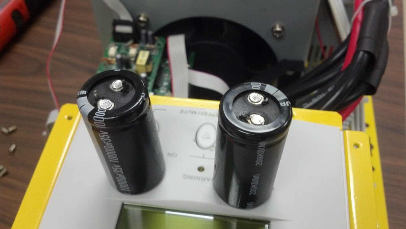
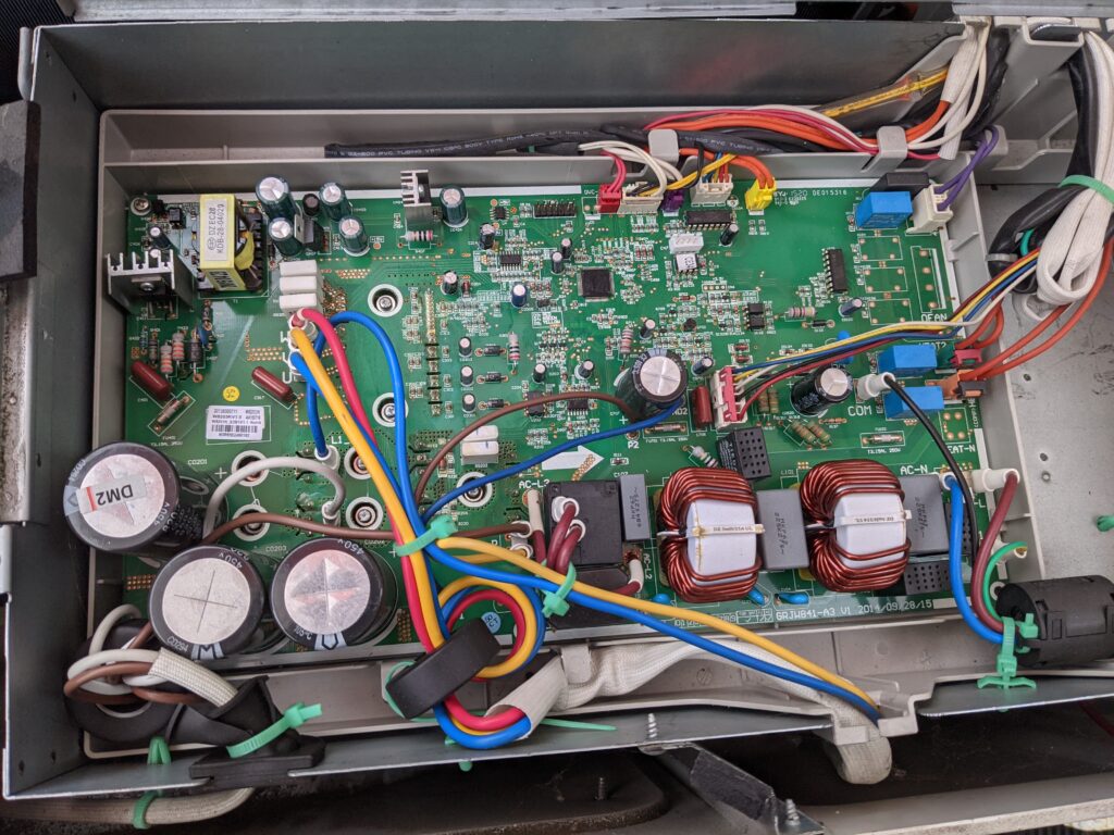
The main control PCB lives in the outdoor unit (the indoor unit being powered through this as well). I removed power, cracked the lid, and was greeted with a nice surprise.

Outdoor Unit Cover Removed, Easily!

No real difficulty getting thus far and very happy to see what appeared to be the main control board cover right at the top! Somewhat ironically, the error code list sitting right there, obvious, while I was scouring the internet for diagnostics information.

Error Code List with LED flash codes

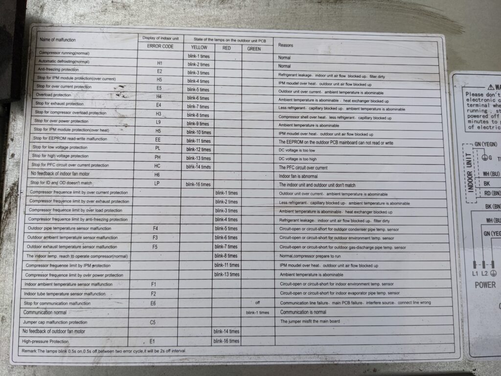
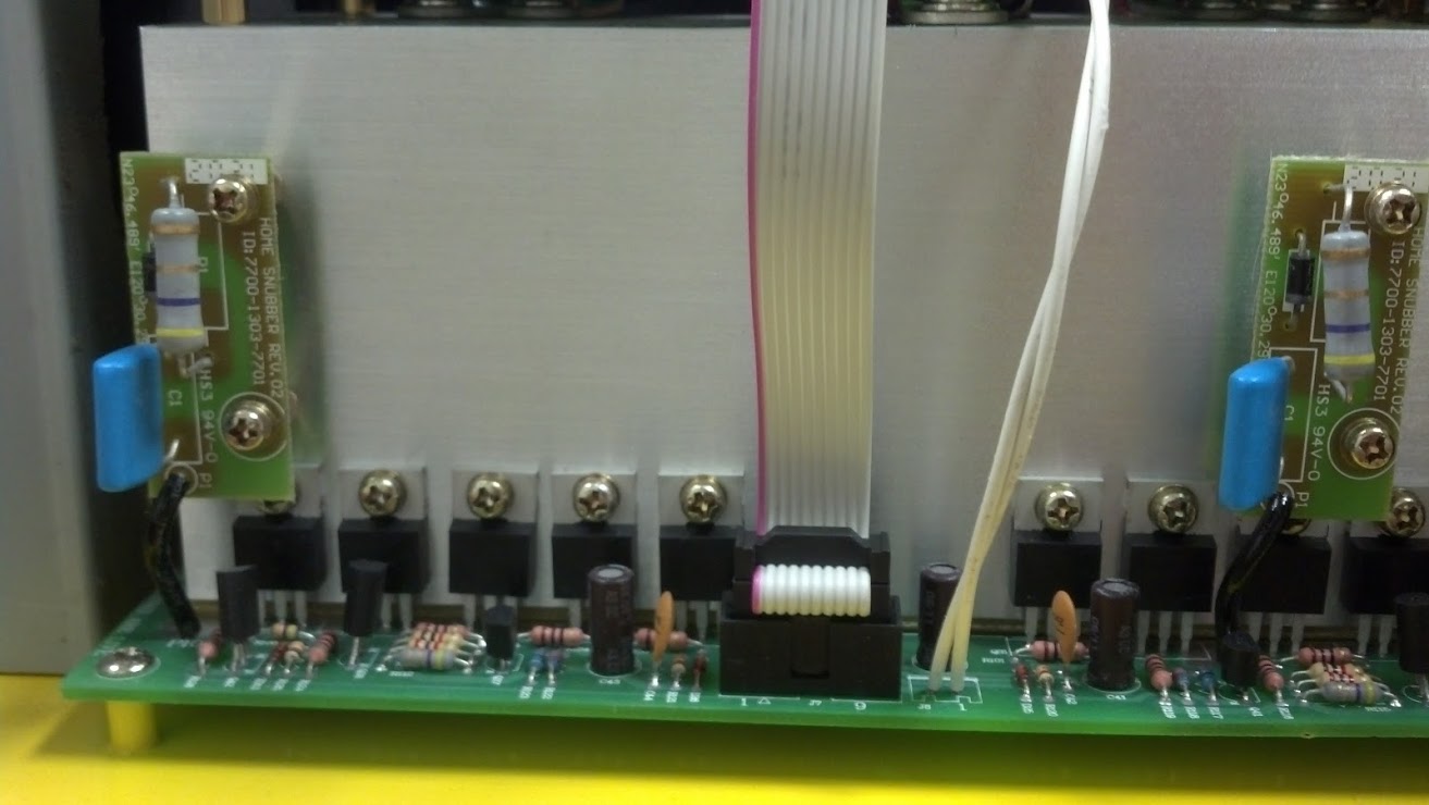
This is particularly useful, and hopefully helps others in the future as well that might be looking for codes before opening up their unit. I confirmed that the indoor unit “E1” code indeed meant that the unit thought it was in an overpressure state. Checking the wiring diagram nearby, it appears there are two pressure sensors (Normally Closed) that open when a high pressure condition occurs. Probing the two sensors on the board (OPP and OPP1) showed that there was 5V across one, and 0V across the other. OPP, plug pulled and continuity checked, was open and indicating a high pressure fault.

Main PCB with LED’s in the center

Having a closer look at the sensors, it appears that OPP has a higher pressure setpoint than OPP1. This would indicate to me that since OPP1 is not indicating an over pressure condition, OPP has an open in the wiring or the sensor is failing. To confirm this, I placed a alligator clip across the two pins on the PCB, effectively telling the board that OPP is “OK” and to start the unit. The error code cleared, the red LED started blinking 8 times (normal condition of operation), the green LED said I had communication with the indoor unit, and the compressor/fan started to run. Excellent.

Rainy day diagnostics working under an umbrella

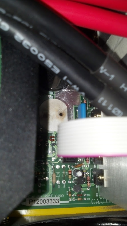
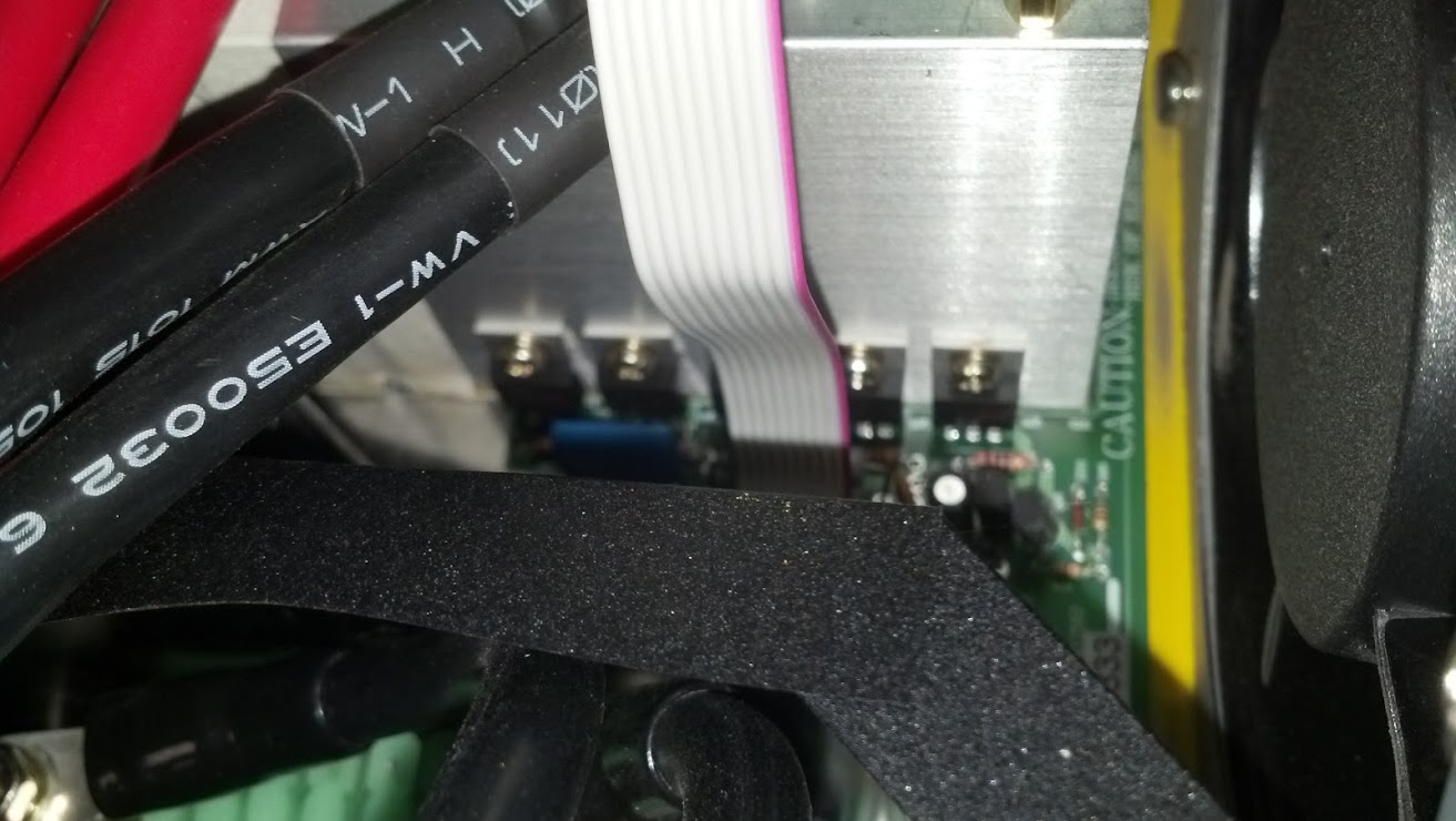
Now to move down to the sensor, I pulled the front cover off (a couple more phillips head screws) and followed the cables down to the respective sensors.

OPP (red) on top, OPP1 (green) on bottom, Electronic Expansion Valve top and center

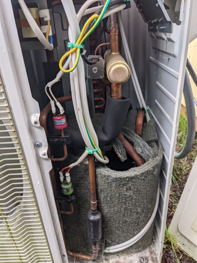
Wiggling connections, it appears there may be a loose spade terminal at OPP (red sensor) that could perhaps be causing the open condition? This line sees vibration from the fan and compressor, and was showing continuity when I checked it again after jumping the pins on the PCB. I cleaned the terminals and re-connected the sensor.

OPP has a valid part number 46020006

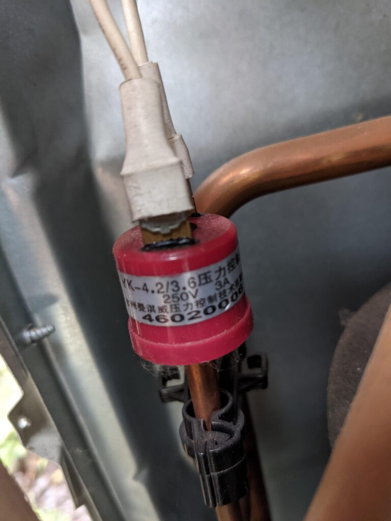
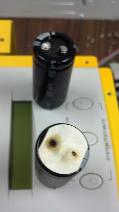
I snagged a photo of the sensor before moving forward incase I need to replace it. Unfortunately this sensor is brazed in place, so would require a full system evacuation and re-charge. This part number is a valid, and available across the web fairly cheaply (<$20)

OPP1 below, apparently working just fine

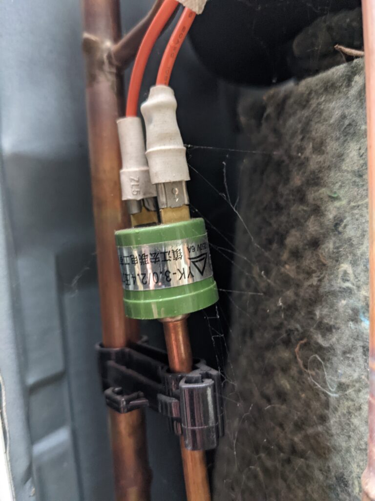
OPP1 below tested good and appears to be working fine. No issues there so left well enough alone.

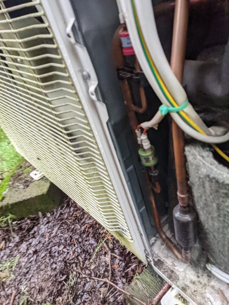
These two sensors are very easily accessed and should be not too terrible to replace if I need to do so later on. Brazing in tight quarters gets tricky so I appreciate that these aren’t buried into the enclosure, surrounded by flammable objects. I will report back later if this terminal cleaning did the fix or to expect a sensor replacement post in the near future. To keep things running (unit keeps the shop humidity controlled and above freezing) I may bypass the high pressure sensor until I can do the fix, understanding that the lower should activate first (and is unlikely to do so during the winter after 4+ years of operating normally). Thanks for following along!

Community Power Pods

I recently stumbled across and have grown interest in supporting a very interesting project inline with my interests! https://www.gofundme.com/f/powerpodspdx

Introducing our prototype Community Power Pod, a Do-It-Yourself 1500 watt, 3000Wh portable generator utilizing secondhand battery modules from the Chevy Bolt EV. The pod is solar rechargeable and has quiet, fume-free operation, allowing it to be used almost anywhere! I’ve been helping a team of makers in Portland develop this open source community aid and disaster relief project, aimed at increasing access to this renewable technology for under served populations and those affected by natural disasters or other crises. We are working to build a fleet of these which can be deployed to support community members in need, and with the recent pandemic and wildfires that need is greater than ever. Our generator has been used for weeks now to support COVID-safe outdoor public events, fire relief efforts, and community aid projects.The power pod cost us around $600 to construct– a fraction of the price of commercial alternatives. The team hopes to build more of these ASAP, as well as share our knowledge and resources with groups in other cities so they can replicate and build upon our work elsewhere. However, at the moment we are working to find a new source for our Chevy Bolt battery modules, since the original supplier has sold out. More updates forthcoming once we can figure this out!

-CommunityPowerPods Team

PGE – Peak Time Rebates – Use Less Energy, not Zero!

Being recently made aware of the program offered by our local utility Portland General Electric, I decided to enroll in Peak Time Rebates and try my hand at saving a few bucks on the next bill (and lightening the load on the grid during some heavy-usage times). A couple opportunities presented themselves in late July, which I partook in, however have yet to see the benefits reflected on my bill (up to $1 per kWhr saved during the event, as per the PGE website).

A day prior to the first event, I received text & email notification of an upcoming Peak Time Event scheduled for 5-8pm July 21st, 2020. I decided to see if I could move my home power usage during the event to zero without any significant fallout. With ample warning, I prepared my various systems for 3hrs+ of offline time, ensuring that battery backed devices were up to the task and that the few non-battery backed devices were moved over to independent power sources. This was fairly easy given that I’ve been creating an overabundance of energy lately but have nowhere to send it (read as – not grid tied). The only large consumers in this category were items like refrigeration, fans, etc.

5pm on the 21st rolls up and I was a little late getting home so didn’t start shedding loads until closer to 6pm. Early in the second hour of the event I had reduced my energy draw to zero, without any adverse effects. This meant shedding the AC, Heat Pump Water Heater, Spa, items like that. Refrigeration was brought onto the independent solar grid for the duration of the event. The meter stopped ‘turning’. Yay!


Late to the Party

After 8pm passed, I powered back on the desired devices (AC, fans, water heater, etc) as can be seen in the graph. Temperature gain in the home was notable but not uncomfortable. My house, being built in 1915 has less than ideal forms of insulation in walls and ceiling (if any at all). Fortunately the finished basement remains it’s fairly standard 17-18C; a nice refuge if things get too warm on the main floor. I felt accomplished with the experiment and waited for news as to what my rebate savings would be (typically sent via email/text as well).

Those results never came.

For comparison, the next day (typical high-end of power load for my home and accessories).

Typical Day as a Comparable

I didn’t think much of the event until I started hearing reports that other folks were receiving their rebate information (or that they didn’t reduce enough to qualify). Another peak time event text came through, this time for the 30th of July, so I prepared once again.

This round I was able to start earlier, though still a bit behind schedule due to some visitors. Similar setup, battery backed items were easily shed and the refrigeration moved to my alternative energy source. I made a nice big dent in the power draw during the 3hour window, raising interior temperatures 3-4C but still tolerable for inhabitants. Nearly hitting the zero-power-used mark for the time period, I felt fairly accomplished.

Fashionably late

Fast forward to 2nd week of August, and I still haven’t heard the results of my efforts. Nothing on the PGE website about my peak time events being successful (or denied)…just a blank window.

…perplexing…

Bummer. Starting to wonder if their system ‘broke’ when it saw the zero and/or too-near-zero values that it flagged it requiring review before applying rebate. Given that the average layperson isn’t familiar with the small loads associated with wall-wart style power packs or smart device draw even when off, I guess I could understand. So I called PGE up.

The associated I talked to (Robert) was understanding and although a bit confused himself, had access to internal FAQ materials that advised him to let me know that zero usage during a time period makes the program assume there was a outage (or something of that sort?) that would render the data ineligible for the PGE Peak Time Rebates program. He kept asking “did you turn off the breaker?” Having not found anything indicating that zero usage would invalidate the rebate option, I was (and continue to be) confused but realize that this person likely won’t have the solution I’m looking for. I asked that if were able to flag my account for review AND also please present more accurate terms and conditions for the program on the website, it would be appreciated. Frustrated, but not going to take it out on a support person, I completed the call and pondered my next move.

Twitter?

I logged into my old Twitter account and searched for Portland General Electric, ready to shine some public light on my experience and see what comes of the effort. With little to loose other than them possibly deciding they don’t want to provide me energy anymore, I figured it was worth a shot.

I guess this is what we do these days?

I was contacted publicly by a representative (Sonja) who explained eloquently:

Helpful information, but not on their website or terms…

A bit of back and forth ensued, and the end result was that I was forwarded to Elaine, who was putting my situation in front of an Advisor and they would be contacting me soon. Fingers crossed for some resolution? I’ll update as I find out more.

Update:
Pinged them again on Twitter and got a reply later that day:

Even though my meter was indicating data (in some cases zero, some – reduced usage) apparently PGE will flag the period as an ‘outage’ if there is zero kWhr used during any of those hour blocks. This decision is in reply to disclosing that my ‘essential’ home loads were powered alternatively and anything battery backed was effectively ‘shifting’ the draw outside the window, charging batteries after and precisely meeting the goal the outlined for the program.

The summary? If you’re going to save energy, make sure you don’t save too much.

Glenn Martin MT-1845 Tower Documentation

I had a difficult time finding this documentation so I’ll post it here for anyone whom may need it in the future.


This is for a Glen-Martin (G-M) MT-1845 50ft crank-up ground-mount tower. This is the same tower found on their TT-1845 (trailer mounted 50ft tilt over tower), but with a base plate for direct ground mounting.

PDF Document for Base Plate/Concrete Requirements: Chb13-18

PDF Document for Tower Specification Drawings: MT-1845


HB-13-18

MT-1845 1

MT-1845 2

PIP-2424LC Pure Sine Inverter Charger Review

I recently purchased a PIP-2424LC inverter/charger w/ Solar charger off of ebay from the Taiwanese company MPPSolar.

Below is a review of the item (with photos).


We purchased two of these units, one with the network interface module, one without. Both of these units were connected to 24V DC AGM battery banks (two group 8D batteries in series each). They were independently powered from either phase of a 240V drop (each had their own 120V 30A breaker). 200A fuses were used with 00 wire on the DC inputs. The sine-wave from these units was actually quite clean (especially considering the design) and played well with all of our true-sine sensitive devices. We did find that during brownout, the device switched over at too low of a voltage (even though we set it to be 100V) and some servers/computers would actually drop while the switchover was happening. This obviously defeats the purpose of a battery backup inverter/charger for UPS use.

After ~6mo use, one of the units showed DC BUS FAIL and was emitting a terrible smell. It failed into AC only mode (inverter not functioning) so at least the computers stayed online. After working with the vendor (support@mppsolar.com) they advised us to remove the cover and photograph the internals. Below are what we found.

IMG_20130328_100408_052


These are two capacitors off the main DC bus right at the switching MOSFETS. It appears that poor wave-soldering caused intermittent connection, which lead to high resistance and when the units would drop into inverter mode, melting of the solder. These two capacitors were loose in the unit (had unsoldered/burned the leads off). The 3rd capacitor was loose but not fully removed.


IMG_20130328_100430_151


Wave solder screens under the capacitors were burnt, showing a clear indicator of high-resistance connection. The capacitors were still fully functional when tested.

IMG_20130328_100442_887

A shot of the PCB where the capacitors connect.

IMG_20130328_100458_808


A photo of the MOSFETS showing that they are all in-tact.

IMG_20130328_100517_852

Another shot of the MOSFETS on the other side, again all in-tact.

MPPSolar wanted us to ship them the PCB board so that they could then ship us a replacement (meaning even more downtime, even more expense, and us doing all of the labor in-house). Purchasing these units from outside the country is the risk you take and in this case, that was a bad choice.


In summary we determined that poor wave soldering on this unit resulted in premature failure. The difficulty in configuring the voltages at which the unit goes into changeover can be a large issue for people with sensitive electronics or applications where 100%  up-time is a requirement. I would suggest not to waste the money on these units as even though the tech support team is good with communication, you will find yourself shipping parts to/fro Taiwan on your own dime.

I would also HIGHLY suggest never using one of these units in a mobile application as the construction methods and soldering type is not adequately stable for longevity.

Connecting Ubiquiti Aircam to Synology NAS – Surveillance Station 6.1-2941

How to:

This requires you to modify .conf files on your Synology NAS. If you are not familiar with how to do this or are not good in a UNIX terminal, you may want to investigate adding this package to your NAS before starting (for file editing): http://mertymade.com/syno/#cfe

Make sure both your UBNT Aircam and the Synology NAS are running most current (current date 2/20/2014) firmware/packages.

Start the SSH service on your NAS if you wish to SSH into it using Putty or some other flavor of client. Do this by logging into your NAS, selecting Control Panel, then clicking on Terminal. Select ‘Enable SSH service’ and click apply. Confirm that Surveillance Station 6.1 is already shut down before editing files (you can confirm this in the package manager)

SSH into your NAS by entering the IP address and using the default port. Username:  root, password: admin

Example: Type ssh root@192.168.1.2 hit return and then wait for prompt and enter the password “admin”. Replace the IP address with your NAS IP address and if you have changed your root password (you really should) it will be something besides admin.

Navigate to and edit the following files (I used the vi command followed by a space and the file name):

/volume1/@appstore/SurveillanceStation/device_pack/

camera_support/camera_model.conf

Add under the {camera*list] (using vi, you click the insert button on your keyboard and then scroll up/down):

[camera*list]
UBNT*Aircam=UBNT*generic
D-Link*DCS-900=D-Link*generic
D-Link*DCS-2121=D-Link*generic-gr1
LINKSYS*WVC54GCA=LINKSYS*generic
TRENDNet*TV-IP100=TRENDNet*generic-gr1
TRENDNet*TV-IP100W=TRENDNet*generic-gr1
TRENDNet*TV-IP100-N=TRENDNet*generic-gr2
TRENDNet*TV-IP100W-N=TRENDNet*generic-gr2
TRENDNet*TV-IP212=TRENDNet*generic-gr3
TRENDNet*TV-IP212W=TRENDNet*generic-gr3
TRENDNet*TV-IP400=TRENDNet*generic-gr1
TRENDNet*TV-IP400W=TRENDNet*generic-gr1
TRENDNet*TV-IP410=TRENDNet*generic-ptz1
TRENDNet*TV-IP410W=TRENDNet*generic-ptz1
TRENDNet*TV-IP512P=TRENDNet*generic-gr4
SparkLAN*CAS-335=SparkLAN*generic-gr1
SparkLAN*CAS-335W=SparkLAN*generic-gr1
SparkLAN*CAS-633=SparkLAN*generic-gr2
SparkLAN*CAS-633W=SparkLAN*generic-gr2
SparkLAN*CAS-673=SparkLAN*generic-ptz1
SparkLAN*CAS-673W=SparkLAN*generic-ptz1
Sony*SNC-RZ30N=Sony*generic-gen1-ptz
Sony*SNC-RZ30P=Sony*generic-gen1-ptz
Sony*SNC-Z20N=Sony*generic-gen1-z
Sony*SNC-Z20P=Sony*generic-gen1-z
Siemens*CCIC1410-L=Siemens*generic-gr1
Siemens*CCIC1410-LA=Siemens*generic-gr1
Siemens*CCIC1410-LAW=Siemens*generic-gr1

Then add, down below where the camera port/streams are called out:

[UBNT*generic]
      port=554
      video source=”/live/ch01_0″
[D-Link*generic]
port=80
video source=video.cgi

etc.

Use ch00_0 for higher resolution video.

You then need to save that file (in vi, hit Esc, followed by a colon, followed by the letters ‘wq’ and then hit enter.

Next edit the following file:

/volume1/@appstore/SurveillanceStation/device_pack/

camera_support/UBNT.conf

It doesn’t exist (it will be blank and empty) however if you use VI (or similar editor) and save the contents, it will create the file for you.

Within that file, paste the following:

[UBNT*Aircam]
api = ubnt

channel_list = 1

default_channel = 1
resolutions_h264 = 640×480, 1280×720

default_resolution_h264 = 1280×720

fps_h264_[640×480] = 5,10,15,20,25,30
fps_h264_[1280×720] = 5,10,15,20,25,30
default_fps_h264_1280x720 = 10
default_fps_h264_640x480 = 10
default_image_quality = 5

h264 = rtsp

default_username = ubnt
default_password = ubnt

(Again, if in vi, hit Esc, then enter ‘:wq’ and hit return to save)

Restart your Surveillance Station 6.1 package and go add a new camera.

Select UBNT and Aircam.

Name your camera, enter port 554, your proper IP, and H.264 as your video type. Username and password need to match what you have set up on the Aircam in the web interface under video, RTSP Authentication (username/password). Synology only includes one free camera license per NAS unless you buy additional licences through them (search the web to find out more).

Hope you enjoy having your NAS directly talking with your Ubiquiti Aircam.

Thanks,

MEP-006A Exciter Diodes

Here are the two diodes I selected to replace the failed ones in my MEP-006A Military 60kW generator.

http://www.mouser.com/Search/ProductDetail.aspx?R=1N1190Avirtualkey66430000virtualkey905-1N1190A

http://www.mouser.com/Search/ProductDetail.aspx?R=1N1190ARvirtualkey66430000virtualkey905-1N1190AR


You would need x3 of each and I recommend getting a spare if you aren’t familiar with proper torque and are prone to breaking studs off components. One is a reverse connection of the other (designed 1NxxxxR)


Specifications:

1N1190 / 1N1190R Data Sheets


Three of one type are on one side of the aluminium rectifier mount, and the other three are on the other side. Make sure you use plenty of thermal conduction grease when making the connection.

Generator Project Update

The generator (MEP006A) had a power-off failure recently.

Upon investigating, found that the exciter had received some serious overcurrent (melted the soldered connections on the diodes on the exciter winding) as well as may have fried something inside the excitation module above (big green box).

Need to perform triage and figure out what happened…but hopefully have this back online soon.


Upgrades thus far:

  • Replaced Primary Fuel Filter with Dual Element Glass (like on John Deere Industrial)
  • Replaced Secondary Fuel Filter with Single Element Racor Spin-On
  • Changed Oil
  • Changed Oil Filters
  • Checked Valves
  • Rebuilt Injection Pump (had bad seals on shaft and rubber coupler…very common)
  • Replaced bad fuel lines
  • Cleaned Connections on Fuel Pumps (problem area)
  • Serviced Cooling System (CAT Long-Life Coolant 50/50)

I am also working on building a tandem axle trailer just for this unit. The axles/rough frame was donated by one of the family friends Tony. Removed the decking (rotten) and narrowed the axles/frame by 1.5ft and shortened it considerably. I purchased new bearing kits, two new drums, four electric brake backing plates, and two new tire/wheel combos. I also purchased some upgraded lighting (LED all around) and trailer connectors/etc.  I got all 24V compliant lighting so I can power basic proximity lighting on the generator while it is running on a job-site or parked precariously. It will have a new frame horn (heavy duty) and unless stolen, jacking points on all four corners. I would like to do locking cable/tool boxes to store various associated items.

That is all for now! More updates when I find out what let the smoke out.